Flagpole Installation
|
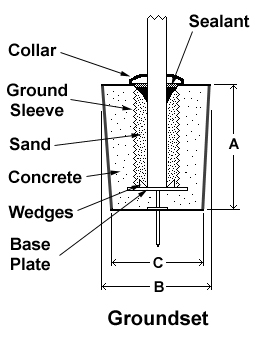
GROUND SLEEVE FLAGPOLE INSTALLATION The embedded, or Ground set mount is the method of choice for mounting most aluminum and fiberglass flagpoles. Be sure to refer to the chart at the bottom of the page for your hole depth according to your flagpole height. Before You Dig… • Read though these instructions and make sure that you have all the components and tools required for the installation. |
|
|
Tools and Accessories Required – Not Included • Level *NOTE: Depending on the flagpole that is purchased, the ground sleeve may be PVC or Galvanized Steel. |
|
 |
|
|
1. Dig foundation as detailed in the Ground Sleeve Installation Instructions listed above. Set sleeve into hole so that top of tube is 2″ above grade. Plumb sleeve vertically and brace so that sleeve will not move during pour. Pour concrete and trowel to desired finish. Keep inside of sleeve dry and free of concrete. Cover top of sleeve if shaft has not been delivered. 2. Lay shaft on sawhorses, and remove wrappings from top and bottom of shaft, and from around cleat area. Leave balance of wrappings on shaft for protection during the set. If pole is two or three piece, assemble sections per instructions on reverse side. 3. Screw truck into top of pole, using pipe wrench to tighten. Screw threaded ball-stem into top of truck until ball will not turn further. Using wrench, tighten jam-nut against top of truck. Thread one end of rope halyard through the truck pulley and tape or tie ends of rope together. Flag snaps may be attached after pole is erected. (If pole is double halyard system, repeat operation for second halyard.) 4. Using screws supplied, mount cleat(s) to shaft over drilled and tapped holes approximately 5′ above tar-line. (If cleat covers are used, mount them at the same time, using the same holes.) Slip collar on bottom of shaft, and temporarily tape it to wrappings above tar-line. 5. Pick up shaft with nylon sling, rotate pole so that cleats will face in the desired direction, and set into center of foundation sleeve. If pole is two or three piece, a nylon choker must be used to prevent the bottom section from slipping off when lifted. Plumb pole vertically. Place wood wedges (not supplied) between pole and sleeve to prevent pole from shifting during final set. 6. Tamp dry sand between pole and sleeve to permanently set pole. Be certain that sand is well compacted, otherwise pole may shift at a later time. Leave a 1″ to 2″ void at top of sleeve for sealer. Remove wedges, fill void with waterproof cement or sealant, and slip collar down pole onto concrete. Caulk into place on concrete, and around pole. Remove remainder of wrappings from pole. 7. Attach flag snaps to halyard by forming a loop in the rope, running the loop through the swivel-eye and over the snap, then pulling rope taut. Adjust distance between flag snaps to accommodate the size flag being flown. Attach flag, run to peak, and tie off halyards on cleat. |
|
|
Ground Sleeve Specifications
|
|||||
|
Shaft Foundation Dimensions
|
|||||
|
HEIGHT
|
BUTT DIAMETER
|
SLEEVE DIAMETER
|
DEPTH A
|
DEPTH B
|
DEPTH C
|
|
20′
|
4″
|
6″
|
3′ 6″
|
30″
|
24″
|
|
20′
|
5″
|
8″
|
3′ 6″
|
30″
|
24″
|
|
25′
|
5″
|
8″
|
3′ 6″
|
30″
|
24″
|
|
25′
|
5.5″ – 6″
|
10″
|
3′ 6″
|
30″
|
24″
|
|
30′
|
5″
|
8″
|
3′ 6″
|
30″
|
24″
|
|
30′
|
6″
|
10″
|
3′ 6″
|
30″
|
24″
|
|
35′
|
5″
|
8″
|
4′ 0″
|
36″
|
30″
|
|
35′
|
6″ – 7″
|
10″
|
4′ 0″
|
36″
|
30″
|
|
40′
|
7″
|
10″
|
4′ 6″
|
42″
|
36″
|
|
40′
|
8″
|
12″
|
4′ 6″
|
42″
|
36″
|
|
45′
|
8″
|
12″
|
5′ 0″
|
48″
|
42″
|
|
50′
|
8″
|
12″
|
5′ 6″
|
48″
|
42″
|
|
50′
|
10″
|
15″
|
5′ 6″
|
48″
|
42″
|
|
60′
|
10″ – 12″
|
15″
|
6′ 10″
|
48″
|
42″
|
|
70′
|
10″ – 12″
|
15″
|
8′ 0″
|
60″
|
48″
|
|
80′
|
12″
|
15″
|
9′ 0″
|
60″
|
48″
|


